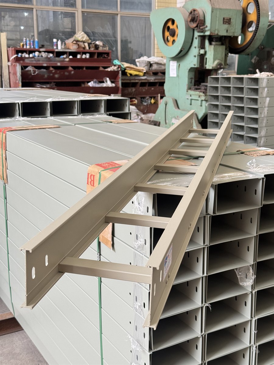
Cable tray thickness is not a load rating. Two products with the same nominal thickness can perform differently because width, side-rail profile, rung spacing, material, splice design and support span change the behavior of the complete system. Buyers should begin with the cable schedule and installation geometry, then review data for the exact proposed construction.
1. Six factors that affect a cable tray system
Cable tray should not be treated as a walkway or temporary work platform. Concentrated loads, vibration, wind, seismic actions or unusual support conditions require project-specific engineering.
2. A five-step selection workflow
- Build the cable schedule: record cable type, outside diameter, mass, quantity and approved spare capacity.
- Map the route: identify horizontal runs, risers, bends, branches and equipment entries.
- Define supports: obtain the approved support type, spacing and attachment surface.
- Review the system: compare the proposed construction against load and deflection information for that support condition.
- Check interfaces: confirm fittings, splices and supports match the straight sections.
3. Documents to request from a supplier
| Document | What to verify |
|---|---|
| Construction drawing | Width, side rail, bottom or rungs, and splice design |
| Load/span information | The exact support condition and product family |
| Deflection information | Measurement basis and project limit |
| Material and finish data | Material route and environmental suitability |
| Fitting/support drawings | Compatibility with straight sections |
| Standard reference | Edition, scope and contractual relevance |
IEC 61537:2023 covers requirements and tests for cable tray and cable ladder systems and includes revised safe working load test procedures. NEMA VE 1 addresses construction, testing and performance requirements for metal cable tray systems in its North American scope. Do not treat the two references as automatically interchangeable.
4. Items to verify before installation
- Supports are attached to approved structural locations.
- Splice locations and hardware follow the approved system details.
- Bends, tees and equipment entries receive any required additional support.
- Risers, outdoor runs and vibration zones follow project-specific details.
- The installed cable load remains within the approved design basis.
- Future additions do not consume both fill and load allowance without review.
References and scope note
These links confirm the title and scope of the referenced publications. The project specification, current purchased standard, contract documents and engineer approval remain controlling.
Frequently asked questions
Is tray thickness the same as load capacity?
No. Thickness is one input; tray geometry, width, side height, rungs or bottom, material, splices and support span also affect performance.
Who approves the support spacing?
The supplier may provide product data, but the project designer or responsible engineer should approve the installation support arrangement.
Can workers stand on cable tray?
Cable tray should not be used as a walkway or work platform unless a separate engineered and approved provision exists.
Send a drawing, BOQ or cable schedule
Yunxing can review tray type, dimensions, finish, fittings, supports, packing and delivery information before preparing a project quotation.
Request a quotation