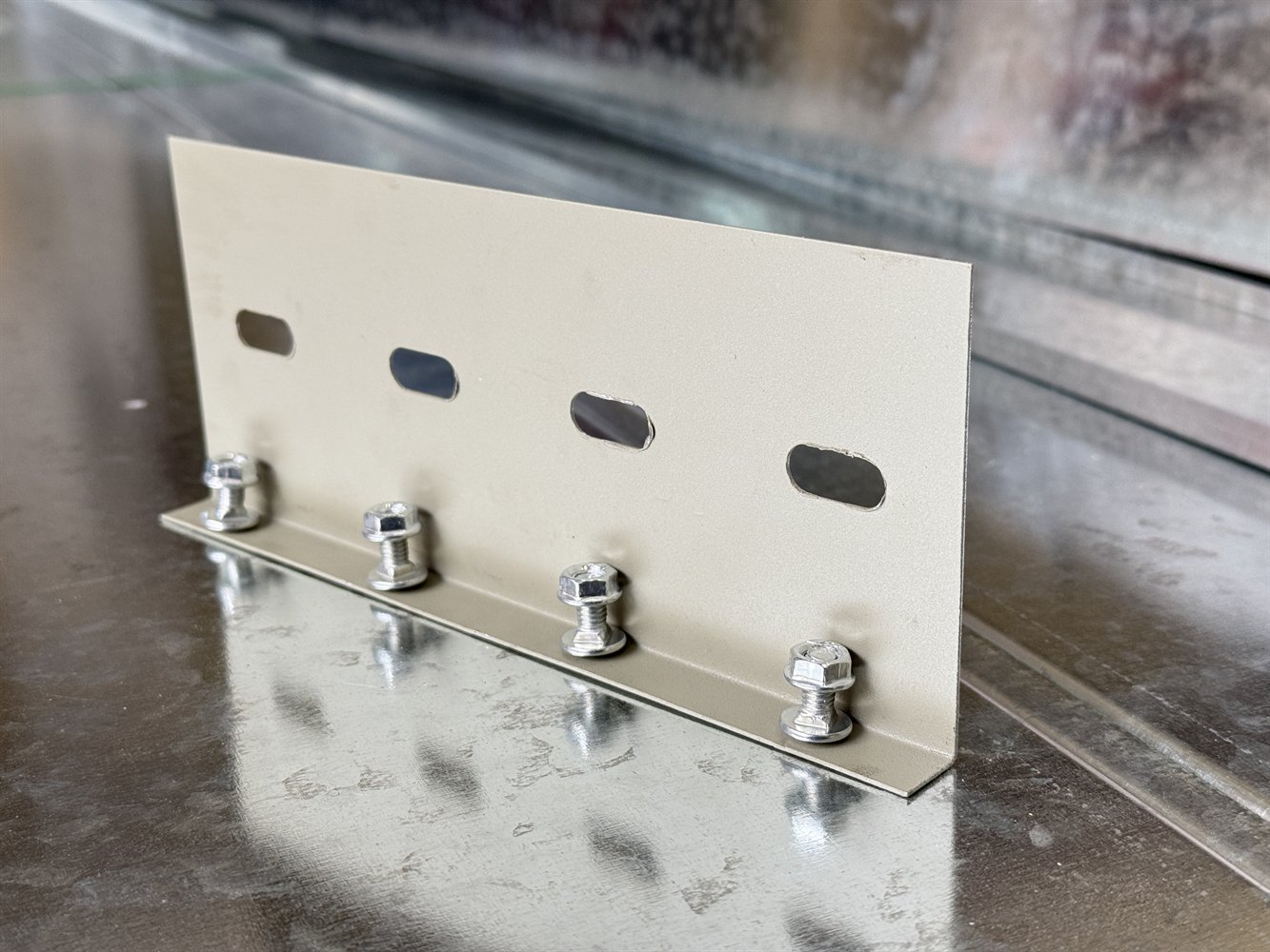
Straight tray length is only one part of a complete cable management route. Bends, tees, crosses, reducers, covers, dividers, splice plates, fasteners and supports are frequent causes of late purchase orders. The accessory schedule should follow every route change and equipment interface on the drawing.
1. Typical accessory categories
| Category | Typical items | Buyer check |
|---|---|---|
| Straight sections | Standard and special lengths | Type, size, thickness and length |
| Horizontal direction | Bends, tees and crosses | Angle, hand and radius |
| Vertical direction | Inside/outside riser bends and vertical tees | Orientation and available clearance |
| Reducers | Straight, left-hand and right-hand reducers | Start/end size and offset |
| Coverage/separation | Covers, dividers and hold-downs | Length, fixing method and height |
| Connections | Splice plates, bolts and bonding items | Material, quantity and compatibility |
| Supports | Brackets, threaded rods, trapeze members and bases | Approved support detail and spacing |
| Interfaces | End plates, drop-outs, edge protection and expansion items | Equipment entry and special locations |
2. How to take off accessories from drawings
- Divide the route by level, area or system and assign route references.
- Measure horizontal and vertical straight runs and mark non-standard lengths.
- Follow the route and record every bend, branch, reducer, wall crossing and equipment entry.
- Measure the exact length requiring covers, dividers or weather protection.
- Count supports from the approved support plan, not from an assumed spacing.
- Reference each custom fitting to an approved sketch or fabrication drawing.
For risers, equipment rooms and large fittings, a pre-production drawing review helps prevent left/right or elevation errors.
3. Six frequently omitted items
4. Pre-shipment accessory review
- Every fitting size matches the connected straight sections.
- Direction, angle and radius match the approved drawing.
- Covers, dividers, splice plates and fasteners are counted separately.
- Material, coating and color match the agreed system.
- Custom fittings carry drawing references and package marks.
- Small hardware is boxed, labelled and tied to the packing list.
NEMA VE 2 treats installation as a system activity and addresses supports, connections, field work and access. A procurement schedule should therefore aim for an installable system, not only a total number of straight metres.
References and scope note
These links confirm the title and scope of the referenced publications. The project specification, current purchased standard, contract documents and engineer approval remain controlling.
Frequently asked questions
Are splice plates and bolts always included?
No. Supplier scope varies, so the quotation should state the included hardware quantity clearly.
Can all bends be fabricated on site?
Some field adjustment may be possible, but engineered routes and complex fittings should use approved compatible parts and qualified installation methods.
Who defines bonding accessories?
The project electrical design and applicable code should define the bonding method; the supplier can then match the confirmed specification and quantity.
Send a drawing, BOQ or cable schedule
Yunxing can review tray type, dimensions, finish, fittings, supports, packing and delivery information before preparing a project quotation.
Request a quotation